Amplifiers are not easy to build. Not only is it tough to find a suitable design to steal off of the internet, it is also difficult to obtain all of your necessary parts, to connect them without explosion and tears, to test them over and over and over, to solve why the sound is so nasty, to go without shorting cables while it is live during prototyping, and to get the heat-sinking perfect. Forget all of that, it is menial if you have to design your own circuit because your sights are set too high for convention! However, it is attainable. This little memorandum will explain it all.
The initial thing that you must decide is what your amplifier will be used for. Other than an ottoman or a fine end-table, what might you be calling upon your amplifier for? Here, I had in my mind from the start the necessity for musical instrument amplifier, namely for the bass. Although this is an extremely difficult amplifier type to build, it has been achieved. The key to this type of amplifier is low-frequency stability, good clipping recovery and, as always, a good DC output offset voltage, which was quite a cinch to solve. In my situation, I had on my hands two ten-inch, 750W sub-woofers, both of the same model and of quite outstanding quality considering that I was able to purchase them for only $50US each. They are figured below.
The nominal impedance of each speaker is 4 ohms. They have but one voice coil [all the less to screw up] and are very powerful in their own right. They came in state-of-the-art bandpass boxes with cool little neon light rings. With a mere 100W RMS in them at one time, they easily created enough noise in the trunk of my car for any neighbors to be able to satisfactorily experience. My idea, however, was to go a step farther than anyone who builds amplifiers as a hobby normally does. I was to wire them in parallel, creating a 2-ohm load and thus a very possibly-loud system. The key, however, was an amp that could take such a hit.
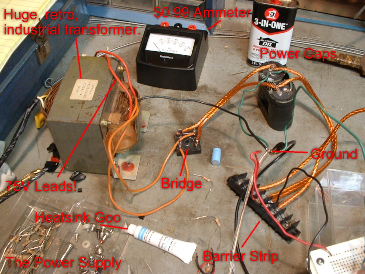
I had a massive transformer on hand, a big 35A bridge rectifier and two 7600µF power supply caps, pictured below. The transformer had two rails after rectification, a ±32V and a ±70V. I threw the 70V rail out the window [not literally]. I was not going to want to go to another galaxy to get output devices that would be able to sustain the kind of current and power that that would create! [Just for interest's sake, that would create about 2.1kW. If I ever build one like that or even find a power supply that could sustain that, you can call me "God."] So I used the 32V pole. Simple enough. Considering a little limitation before clipping, I figured a nominal peak power of 425 watts. That's a lot! Sinking that into two 4-ohm subwoofers would really rock the house, so I was enthused to continue on.
After reading many of my father's old electrical engineering textbooks from his college days, I was saddened to find that nowhere in the seventies did anybody document power amplifiers that delivered more than 0.75 watts. So I took to the internet. Finding a few cool places, especially sound.au.com, I was pleased to find an actual interest in building such devils, what it would take to power my woofers. So I read and researched, working only with paper and calculator, for over a year and half. Then I found Mouser.
This supplier was able to contribute everything to my cause that I needed, not, however, without a small fee. I wrote up my dream-list and had my mail-order girlfriend send it in for me. [She was not a "mail-order girlfriend," she was just very experienced with online business transactions.] Within a few days, the package arrived. I got six 2N3055s and six MJ2955s as output devices, both of which are cheap, reliable and dispensible if necessary, and some TIP31Cs and TIP32Cs for the drivers. I made sure to get some extras as I knew that I would miswire something and blow up some of my devices. A tip of the day: don't test your amp live with a speaker before you get the offset okayed.
During the long process that it had taken to build this amplifier, I had obtained a few speakers from local yard sales and was able to build and outfit a large and in-charge speaker cabinet that is photographed at left. The cabinet has two 15 inch sub-woofer/woofers, a 12 inch all-around woofer and a 10 incher that has really nice high-frequency response. I encased these in a finely-crafted cedar enclosure of my own construction that is five feet tall and three feet wide, with one foot of depth. It also has four Helmholtz holes in it that make the resonance of the box much lower than any note on my bass, so I don't have to worry at all about resonance problems.
With the amplifier under question giving each of these speakers its own 100W, this thing would be audible from space. The white in the back of the response holes is quilting batting, which I stuffed the entire box with to give it better low-frequency response. As you can see, the cabinet was tested with quite pleasing results with the "worthless" amplifier. It gives what I would say about 90dB with 1.25V into the cabinet at a distance of about two metres. So the cabinet is pretty efficient. Now is the time to give it some real juice!
So I needed a design to go by. I found the output stage design in a nice little book I got at a library book sale entitled "Transistor Circuit Design," and I scoured it for ideas. I came up as my final decision to use what is known as a complmentary pair output stage, using two devices per pole connected together to combine their gain, but in a way more efficient and distortion-less than the classic Darlington pair. I had my output stage complete, with a nice bias network of a few resistors and rectifier diodes. I got the stage to work initially with the entire circuit being completely symmetrical, getting a little less than 150mV offset, which was pretty damned good for my first time at actual construction!
I needed some ideas for the voltage gain of the amp. I needed to get at least 28V across my load somehow! Emitter-followers ain't gonna get me there!
After looking over some common designs on the internet, I finally settled on the most common topography of modern amplifier networks. It uses the complementary output pair, along with another gain stage that takes quite a weight off of the shoulders of the second-stage device. Doing this, it basically breaks up the current demands somewhat equally among all of the TO-3 ouput devices. In this fashion, no device goes over 70W at any time in an ambient location of about 25ºC [See Appendix A for an explanation]. I consider this to be pretty safe, since the max specs on the data sheet of a 2N3055/MJ2955 states 115W. We're pretty good.
To the right is a photograph of the forementioned power supply. This thing is a hog! I pulled it out of an old audio power amplifier that had specified operation at 480W total into a few 8 ohm loads, so I knew that this thing would be fine for what I was going to use it for. The bridge I bought at my local, friendly Radio Shack for something like 2.50$US.
So I tested, I tweaked and I researched to find out exactly how a circuit as the one that I had chosen must work to get the results I wanted. I came up with a few epiphanies. They are as follows:
After these all came to my mind, the perplexity that I had was gone. All that you have to do is a little intuitive mathematics to get some initial balance and order in your circuit, play with the values if something is failing you, and get everything hooked up well. Remember, putting in pots to get stuff pin-pointed is not cheating!

This is my basic schematic that lays on the table with my stuff. Q1 and Q2 can be any small-signal transistors that you might have on hand. If you have nothing suitable, you could even go to a Radio Shack and get a couple of 2N3904s or MPS2222As. As long as the transistor has a 40V Vceo rating, you will be fine. Q3 should be a power transistor, something in a TO-220, TO-220A or TO-39 case, whichever you are more comfortable with. I am using a TIP42C, which I also found at Radio Shack! The diodes can be something simple and cheap, but that can take atleast 64V. I am using 1N4004s, which are 1A, 200V devices. Anything in the 1N400* range will work very well, as long as they have a high enough voltage rating for your specific situation. Q4 and Q5 are complimentary drivers, which can be little TO-220s on small, individual heatsinks. You can see them in the photographs. I am using TIP31C/TIP32Cs and they work very well. They have a plentiful voltage capacity and are powerful enough to prevent any meltdown ever. Q6 and Q7 are the larger output transistors. These can be the same type as Q8 and Q9, and will be much more simple for you if they are. These need to have a voltage rating that is at least the voltage from pole to pole. I had used and prototyped with 3055/2955s, but these kept exploding abruptly. For my latest design, I switched to 2N5629/2N6029s, which are much better and are relatively cheap at $2.37US for the NPN and $3.77US for the PNP. You can just look around to find a device that has ratings that you need without emptying your wallet.
Basically, here, setup is not as crucial as most "experts" would like to think that it is. As long as you have some adequate caps in there and a somewhat manageable rat's nest, you'll be fine for protoype testing and jamming. If you don't believe it, look at my very first prototyping setup:
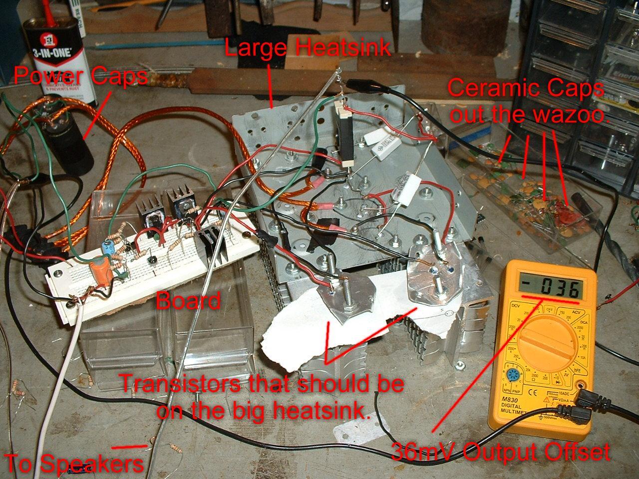
One thing that is wrong with my setup here, however, is that the two transistors being referred to are the second stage of the output stage [Q6, Q7]. They are critical in that they need to be on a large, large heatsink, something with at most 0.2ºC/W. Anything less is dangerous for intermittent to constant play. I was able to test mine for about thirty seconds before the amp started to latch-up from thermal run-away. The only reason that it was like this was for my lack of transistor mounting kits. Radioshack must have though that it would be funny to stop carrying them just as I needed them.
And yes, that does say 36mV offset. That is after the amp was on and tested for ten minutes. It is normally between 6mV and 12mV at power-up with an active signal applied. A close-up of the board shows how non-critical setup can be:

The pot in the tail of the LTP can be seen, and has been adjusted to give minimal offset at the output. The class-A driver and the two output drivers are shown on small Premium Radio Shack heatsinks. These are superb for the purpose at hand, and quite affordable at $0.99US on the clearance rack! The big orange cap is all that I had for my input cap, which I want to be quite large just to make sure that my initial working signal is as clean and manageable as Mandy Moore's hair. I think that the devices that I am using in the LTP in the photograph are 2N5179s, which are very foreign to me but came in an assortment I purchased at Radio Shack and came to suit my situation perfectly. The circuit was simulated with 2N3904s, but a small-signal transistor is a small-signal transistor. This is as complex as it gets. After seeing this, why not build one?
During all of my testing, I have exploded many good transistors. I have even managed to ruin a few pairs of 115W output devices. How is this possible? Live testing with a load attached. Never, ever do that. Test offset and all other critical voltages before attaching any kind of load. No matter how bad the offset might be, even if is pretty close to one of the rails, the transistors will be fine until they have to sink current. So make your screw-ups without a load attached, as no harm will be done. And God help you if something goes wrong and the devices sink too much current into your precious speakers.
The most important thing of all, I think, is correct sinking of the output devices. Although this is not difficult to do, it is crucial in the survival of your amp. I live by the idea that overkill is better than killing your transistors. My heatsink is huge for a reason. It must be able to dissipate a max of 425W of power continuously and quickly enough to keep the dice temperature low enough where the transistors do not approach a dangerous level. And I of course want some leeway in case I have to play in the desert on a hot day in August. So I overkill. But, you have to admit, it is a cool-looking setup. Below is a detail of my initial rig.
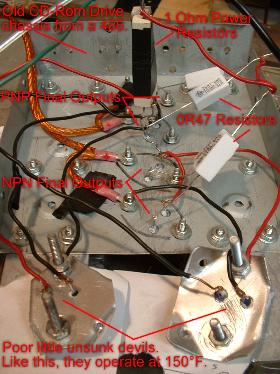
For the safety of your frustration, never sink power output transistors like I have at the bottom of the photograph. It is dangerous. After about 0.5 seconds of live testing, the amp latches-up if the signal clips, since thermal run-away is too much for safety. This can blow the transistors and can blow the load [you dirty-minded man]. So don't do it, no matter how much you want to make heat sinks out of old lids from surplus plastic cases.
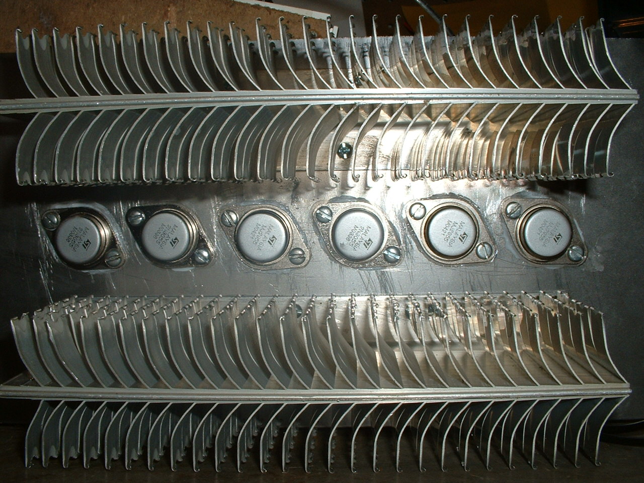
Above is a fine example of how the output devices should be sunk. Look at how pretty that is! You can tell that this one might be a little more stable and operative than the last rig. The key here was to get enough silicone grease on the bottom of the heatsinks before they were mounted to the chassis.
A note about my setup: the transistors that I did most of my prototyping with were 3055/2955s. These transistors, I realized after a few uncalled-for catastrophic disasters, have but a 60V Vceo rating. With my amplifier's voltage rails, all of the TO-3 output transistors were operated where between 58V and 61V would be across the collector-emitters hundreds or thousands of times a second. During one live test with my bass, the amp took a crap and smoke poured out of the heatsink. Q6 had fried from the voltage and sent all of the other output devices to hell with him. I realized after this, doing a bit of research in my simulator, that the voltage rating of the transistors was being threatened. So, I looked around for some replacement parts. I was very pleased when I found the 2N5629/2N6029 complimentary pair from Central Semiconductor, which are very prodigious semiconductors in their own right. These devices have a 100V Vceo rating, which is perfectly fine in my amp, as no more that 64V could ever possibly appear across anything, and they also have plenty of headroom with a 16A Ic limit and a dissipation of 200W at 25ºC. These work much better and will not crap out on me for anything.
As a lasting tip, be liberal with your heat-sinking silicone compound. It's cheap and keeps your rig alive. And what are you going to do with what is left over? Eh?
Now is the time to celebrate! If you have made it this far, you can check off each of the following:
Easy, no? Test and tweak your amp when you can get it to hit. If you have anything that you could not stand when it is finished, you need to do some troubleshooting. Below is a list of problems that I have encountered during the prototyping phase, and that you might, also. Check these first before you do anything stupid.
If this doesn't solve your problem, you can e-mail me and I can posit something up for you, but I would only suggest that you look, re-look and look again at your wiring, because if it works in the simulator, it works when built correctly. If it doesn't work, you know that it is always your fault!
Coming soon, after a quick photography session.
This part was really quite enjoyable! It was truthfully my very first attempt at PCB etching and a really eye-opening one at that. Considering the pain that is sitting over a shoddy little vero-board and trying to connect over sixty little leads without shorting anything, melting anything or ruining anything, I figured I would try this path. It was really quite simple, and even more cheap. I picked up a bottle of FeCl2 at Radio Shack, pictured below:
I also visited the local electronics shop and picked up a 4"x6" one-sided copper-clad board and drew on my sketch initally with graphite pencil, then with a Sharpie permanent marker. A schematic of my traces is below:

I know, it looks like a three-year-old made it. But, it was good enough for me. This is the component-side view. If you want to use this, you may flip the diagram on your computer to get the trace-side view.
Finally, I began etching. What an exciting and fascinating process this was! Below is a photograph of the etching process:
The dark liquid is the FeCl2, and on the board you can see green near the bottom-right corner, which is actually the epoxy resin of the board, indicating correct etching. Where the board turns a dark red-brown is the copper still left on the board. It seemed to be working well! After 35 minutes of "agitating the liquid," the board was completely etched and I flushed the used FeCl2 down the drain. Finally, a picture of the etched board:
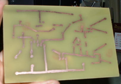
And, you know, it does not really look that complex!
After the etching came the really fin part: drilling. Although this is kind of monotonous, it was also really kind of fun and let the full effect of a nicely-printed board come into effect. Below is a photograph of the board after it has been drilled, and all components in place.
Coming soon.
This is not a difficult task. There are three things that are important when choosing your transistors:
We shall tackle these one at a time.
Due to the nature of operation of the general circuit topography outlined above, output devices will, with a signal that goes from rail to rail or clips, experience a voltage that is double the rail it is attached to. The 3055/2955s that I used at first had a 60V Vceo rating, and I threatened that many times each second. Since I had to test for all situations, I drove the amp hard into clipping. This put about 60V-62V across the transistors, and even more as the amp heated up. Then they exploded. That is not a big surprise. I changed to 100V devices, and it works beautifully. All you have to do for this is to double the value of your supply rail and check it to some devices.
Ic is a little more difficult. Although most home-built projects will be of lower-current, some may not. In my design, the output stage puts between 14A-15A into the load at clipping, maybe more at different frequencies. With three TO-3 output devices, current is split up pretty efficiently. Q6/Q7 takes about 2.5 to 3.5A, and leaves the rest for Q8/Q9, which split the current equally. This will, at worst, leave about 6A for each transistor. They are 16A devices, and will have no trouble with it. If you have a certain device in mind or on hand that might have a lower current rating, use many of them in parallel, anywhere between three or twelve of them, and you should do well. You could even use a tonne of TO-220 devices in the ouput if that's your bag.
The final part is the most difficult to calculate, although the most easy to prepare for. Most TO-3 devices can take at least 100W, and some can take anywhere between 175W and 275W. Although these usually cost much more, they are sometimes worth the price for the piece of mind that they bring. However, we need to know the power in each device. Let's consider, just to find this power, that we have an input signal that is a single sinusoid. From calculus,

So, this basically gives you your maximum output dissipation. As you can tell from the derivative, the maximum power occurs when the voltage across the transistor is half of the supply voltage. This occurs, obviously, when the input signal is half of the supply rail. All you need to know initially is the voltage, load and the number of output devices [Q8, Q9] that you will have. For instance, in my situation, with two final output devices, I have
 .
.
Which tells me that the power in each device will not be more than 60.0625W. Since we live in an imperfect world, and the strange responses that loudspeakers possess, I will consider this to go up to maybe 70W or 80W. If I get some heavy-duty transistors, this figure is rendered insignificant. Also, remember that Q6/Q7 takes a good chunk of the current, so the output power in Q8/Q9 will be less than predicted. This is easy, yes?
Just for clarity of the calclus, the power curves in an output device, with a single sinusoidal input signal, looks like this:

Coming Soon.
You may, for one reason or another, want to know the clipping voltage of your amplifier. This can be used to find the true power output of the amplifier, which everyone seems really interested in. This is not difficult to do. We only need to consider two things: the output stage is altogether an emitter-follower, which we know always has a voltage gain that is less than unity; also, the output resistors at the emitters of the devices will take some of the voltage that is put across themselves and the load. With these two things added together, we can construct a crude formula that can estimate the clipping voltage:
 .
.
This is pretty nifty. All that you need to know is the value of the emitter resistor, in my case 0.1 ohms, the value of your load and the voltage gain of the emitter-follower stages. From general knowledge, the voltage gain from any real-life emitter-follower is between 0.95 and 0.99. Using whichever extreme that you like, calculate your voltage. Worst-case is sometimes a good idea, but with measurement, you can even find exactly what the voltage gain is and use it as a foundation for outher predictions that you might make in the future.
In my situation, this formula gives my clipping voltage to be 28.91V. This is precisely what I have measured, to within ±0.1V!
Ac - Alternating current. Current and voltage that does change with time.
Capacitor - A reactive element that allows ac to cross it but dissallows dc to cross it. It is measured in Farads. See also Reactive Element.
Current - Carrier of electric charge. This is literally the movement of electrons across atoms in some conductive carrier. Measured in amperes (I).
Dc - Direct current. Current and votlage that do not change with time.
Diode - A silicone semiconductor device that has two terminals, a cathode and an anode. It allows current basically to flow only from the anode to the cathode, and requires atleat a 0.65V potential across it to begin operation.
Inductor - A coil of wire the induces a magnetic field upon itself and is able to store energy in the magnetic field. It has a reactive complex that is measured in henrys. See also Reactive Element.
Mains - Voltage out of your wall. This is a 120V sine wave that oscillates 50-60 times a second.
Ohm's Law - One of the most important formulas in electronics. V = IR, where V is voltage, I is current and R is resistance.
PCB - Printed circuit board. A copper-clad circuit board that has been etched to form copper traces that connect components.
Power - Work done by electromotive force in a device. It is equal to the voltage across something multiplied by the current through it. Measured in watts (W).
Power Supply - A network of components that supplies both voltage and current to a usually-resistive circuit. This is commonly a battery or a transformer connected to mains that is rectified and filtered.
Reactive Element - An element whose impedance or resistance in a circuit changes with frequency.
Resistor - A linear building-block of modern circuits. It has a value in ohms, which describes its operation using Ohm's law.
Speaker - A reactive element made from a coil of wire. Its operation is similar to an inductor, but is complicated much more by the mechanical properties of the driver and its enclosure.
Transistor - A semiconductive device made usually from silicone that has three terminals: base, emitter and collector. There are two varieties, NPN and PNP, which describe the polarity of the device's doped characteristics.
Veroboard - A type of circuit board that has a grid of drilled holes that allows component leads to be manually connected and soldered.
Voltage - Electromotive force. The electric potential that causes current to flow through a component. It is analogous to air pressure; varients in air pressure cause wind to flow from higher pressure to lower pressure. Measured in volts (V).
□
Colin R. Mitchell
ColinRMitchell@aol.com
2004